More than just a Plan is this architectural company’s commentary on what comprises a real set of proper Construction Documents.
Copyright 2021 Home Architect, PLLC, All Rights Reserved Worldwide.
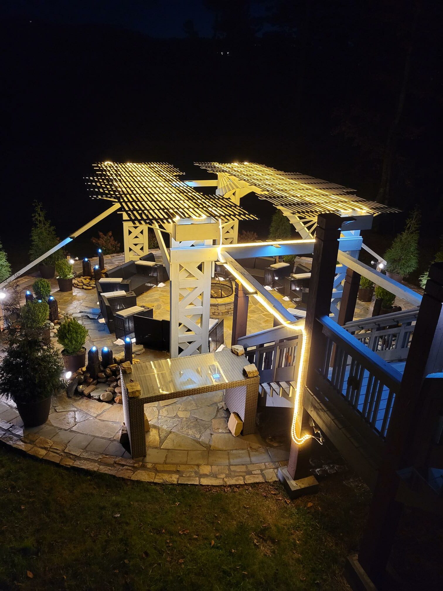
Could anyone imagine building the above with only a “plan?”
Is there a FLOOR PLAN to most Single Family Residential projects? Yes. But unlike many people outside the inner circle of Architecture and Construction, who may think that is the only document or the main document necessary to obtain a building permit and build a custom house, a Floor Plan is only ONE of the documents required.
Usually a Floor Plan is only 1 of perhaps 40 to 75 sheets of drawings. In other words: a Floor Plan is only about 1.6% of all of the documents needed to properly describe the various aspects of what goes into a custom house in order to properly describe it, specify it, detail it, permit it and build it.
Let’s say that again: a PLAN is only about 1.6% of what is required for an Architect to do. Why is this being looked at so closely in this particular online article? Because there are no end of lay people who believe that because they may have scribbled a pencil sketch on the back of a candy wrapper, that they have done the “main work” of what their Architect will need to accomplish. That’s simply uniformed and Not true. In other words, even IF such a “sketch” were a detailed, final construction document, the Architect still has 98.4% of the work to do. And no such “sketch” is ever correct or even works. Why? Because lay people do not draw too scale. They make stairs 2′ x 6′, appliances 18″ square, doorways 20″ wide, beds 4′ square, vehicles 4’x10′ and worse. In other words: usually no such sketch scribbled by anyone not in the architecture and building trades is ever correct. The real Architect will have to work hard to make it functional and in reality will really need to make a new Floor Plan, in much greater detail, and one that is based on detailed PROGRAMMING and proper SITE ANALYSIS, not just a spur of the moment scribble by the uninitiated.
And Floor Plans and all documents prepared by the Architect have to be ELECTRONIC. Usually AutoCad, ArchiCad or Revit. So any sort of paper “sketches” are pretty much worthless and represent absolutely no benefit to the Architect in terms of the time he/she needs to prepare a design and construction document package. Especially if the Architect has to waste time pointing out all the faults and NTS (Not To Scale) areas of any client’s preliminary scribbles, and why it doesn’t work in reality or becomes much more expensive.
Okay, so what are ALL of the final documents often required to properly describe a custom house, if not only the Floor Plan?
Here is just one example of a LIST OF DOCUMENTS:
GENERAL G SERIES
G.1 TITLE & PROJECT CODE DATA
G.2 DRAWING INDEX/DRAWING DATES
G.3 ABBREVIATIONS, NOTES, GENERAL INFORMATION , SITE LOCATION MAP
G.4b 3D IMAGES
G.4c 3D IMAGES
G.4d 3d IMAGES
G.4e 3D IMAGES
SITEWORK A2 SERIES
SURVEYS
A2.1 OVERALL SURVEY
A2.2 INTERMEDIATE SURVEY
A2.3 DETAIL SURVEY
A2.6 SITE PLAN
FLOOR PLANS A3 SERIES
A3.1 1ST FLOOR PLAN
A3.2 2ND FLOOR PLAN
A3.B BASEMENT FLOOR PLAN
REFLECTED CEILING PLANS A4 SERIES
A4.1 1ST FLOOR REFLECTED CEILING PLAN
A4.2 2ND FLOOR REFLECTED CEILING PLAN
A4.B BASEMENT FLOOR REFLECTED CEILING PLAN
ROOF PLANS A5 SERIES
A5.1 ROOF PLAN
ELEVATIONS A6 SERIES
A6.1 FRONT ELEVATION
A6.2 REAR ELEVATION
A6.3 RIGHT SIDE ELEVATION
A6.4 LEFT SIDE ELEVATION
A6.5 GARAGE LEFT SIDE ELEVATION
BUILDING SECTIONS A7 SERIES
A7.1 HOUSE MAIN BUILDING SECTION FRONT TO REAR
A7.2 GARAGE BUILDING SECTION FRONT TO REAR
A7.3 OUTDOOR LIVING AREA BUILDING SECTION FRONT TO REAR
WALL SECTIONS A8 SERIES
A8.1 MAIN WINDOW WALL SECTION AND RELATED ELEMENTS
A8.1b WINDOW WALL SECTIONS
A8.1c WINDOW WALL BLOWUP SECTION DETAILS
A8.2 FRONT PORCH ENTRY WALL SECTIONS
A8.3 GARAGE WALL SECTIONS
SCHEDULES A9 SERIES
A9.1 DOOR SCHEDULE
A9.2 FINISH SCHEDULE
INTERIOR ELEVATION/CABINETRY A11 SERIES (with blow-up detail plans)
A11.1 KITCHEN MAIN WALL ELEVATION
A11.2 KITCHEN ISLAND ELEVATION
A11.3 LAUNDRY ELEVATIONS & BANQUETTE
A11.4 MASTER BATH 1&2 VANITY CABINETS, SHOWER ELEVATIONS
A11.5 BATH 3&4 CABINETS, FIREPLACE ELEVATIONS/PLANS
A11.6 GROOM 5, TOILET5, SHOWER5
A11.7 ELEVATOR LOBBY BASEMENT
A11.10 FIREPLACE ELEVATIONS/PLANS
A11.11 STAIR1, STAIR 2 SECTIONS/PLAN DETAILS
DETAILS A12 SERIES
DIVISION 3 CONRETE
A12.3d GARAGE ENTRY SILL
DIVISION 6 WOOD
A12.6post POST, WALL BASES, WIND POSTS, POST BASES, SHEAR WALL, BRACING DETAILS
A12.6brace DECK BRACING
A12.6cab CABINETRY TYPICAL DETAILS
DIVISION 7 THERMAL & MOISTURE PROTECTION
A12.7c FLASHING EDGE, SOFFIT & SUPR-WALL DETAILS
A12.7x REAR DOOR FLASHING-WALL DETAILS
DIVISION 8 DOORS & WINDOWS
A12.8a3 WINDOW SECTION & SUPR-WALL DETAILS-HYDROGAP
A12.8b2 WINDOW DETAILS – FLASHING TAPE & FLASHING SEQUENCE
A12.8d4 DOOR DETAIL THRESHOLDS
SPECIFICATIONS A15 SERIES
A15.1 SPECIFICATIONS
A15.2 SPECIFICATIONS
A15.3 SPECIFICATIONS
A15.4 SPECIFICATIONS
ELECTRICAL E SERIES
EG.1 ELECTRICAL SYSTEM LEGEND
E3.1 ELECTRICAL 1ST FLOOR PLAN
E3.2 ELECTRICAL 2ND FLOOR PLAN
E3.B ELECTRICAL BASEMENT FLOOR PLAN
STRUCTURAL S SERIES (BY STRUCTURAL ENGINEER)
S3.F FOUNDATION PLAN
S3.1 1ST FLOOR FRAMING PLAN
S3.2 2ND FLOOR FRAMING PLAN
S3.5L ROOF FRAMING PLAN GARAGE (LOWER ROOF)
S3.5U ROOF FRAMING PLAN HOUSE (UPPER ROOF)
S12.2-1 BOULDER WALL SECTION
S12.3 FOUNDATION TYPES
S12.6det STRUCTURAL DETAILS & NOTES
S12.7det TSGD ISOMETRIC
———————–
64 SHEETS +/-.
So: it it very much MORE THAN JUST A PLAN.
Not to mention all the emails, phone calls, material selections, in-person meetings and coordination between all parties.
MORE THAN JUST A PLAN.