Well for Drinking Water is about how this Architect managed the installation of a new drinking water well in western North Carolina, USA.
1. HIRE YOUR WELL DRILLER & BUDGET YOUR WELL PROJECT
There are many ways ignorant people can pollute an entire aquifer, so the County will require that a State Licensed Well Driller perform the well drilling and installation process: to adhere to clean water practices to insure the health of the public and to keep aquifers clean. Find the most reputable company in your area. Do not cheap out. Get the best you can afford. You’ll be glad you did. Allow for MORE cost that your driller tells you. Why: because the final cost is sure to be much more than they tell you at the beginning. Why: because the depth of the well may be substantially deeper than you or they are guessing. You won’t know until you finally hit water (if you do at all).
In these parts, it costs $12.50/ foot to drill the hole in the ground, with nothing else (except the casing). To outfit the well, by adding the well pump, trackhoe trenching to the side of the house, drilling through the foundation wall, running piping & wiring from the well to the house, then into the crawlspace, then to a platform with the driller supplied bladder tank, then connecting the wiring and piping to your existing water distribution system might run another $4,000 to $5,000 or more, depending on the depth of your well, size of pump, distance from house and other variables. For instance: this well hole had to be drilled 860′ deep. Whew. So $10,750 just to drill the hole. That did include a 6″ diameter casing down 5′ to bedrock, then another PVC casing down 25′ inside the first casing, and the well head cap.
For this well, the second step (pump, piping, wiring, trenching, crawlspace work and bladder tank cost another $4,777. So the entire well project cost $15,527. Drilling a well is not for the faint of heart. Any drilling company will tell you (probably in writing) that there are no guarantees that they will hit water. So the entire drilling operation is a gamble.
2. SELECT YOUR WELL POINT
Do this with the input of your well driller. Some people believe that well-witching is the thing to do, complete with bent wires or sticks, held by a soothsayer, who supposedly “lets” the 2 sticks or wires move magically and cross, the intersection of which is the location of an underground stream.
Reality: this well was simply located fairly near to the existing house (35′ away from the corner), in the vicinity of ample water sources in the area, and where there were other good wells within several hundred feet away. Also, this is the mountainous area of the headwaters of a local river that STARTS down the mountain from this particular area, meaning that water for the river was coming from this vicinity. So: chances were high that there was a pocket/aquifer down there.
3. COUNTY HEALTH DEPARTMENT PERMIT
You’re not allowed to drill a well without a County Health Department permit. Cost in this neck of the woods: $350. That not only includes the County inspector checking on the well’s progress, it also includes a State well water quality test, which by itself, after the fact costs around $130. So you absolutely want to know what is in the water you and your loved ones are about to drink. There may be a high pH (too acid). You may also have bacteria and need to have some sort of water purification equipment so you do not get sick drinking the water. Good to know.
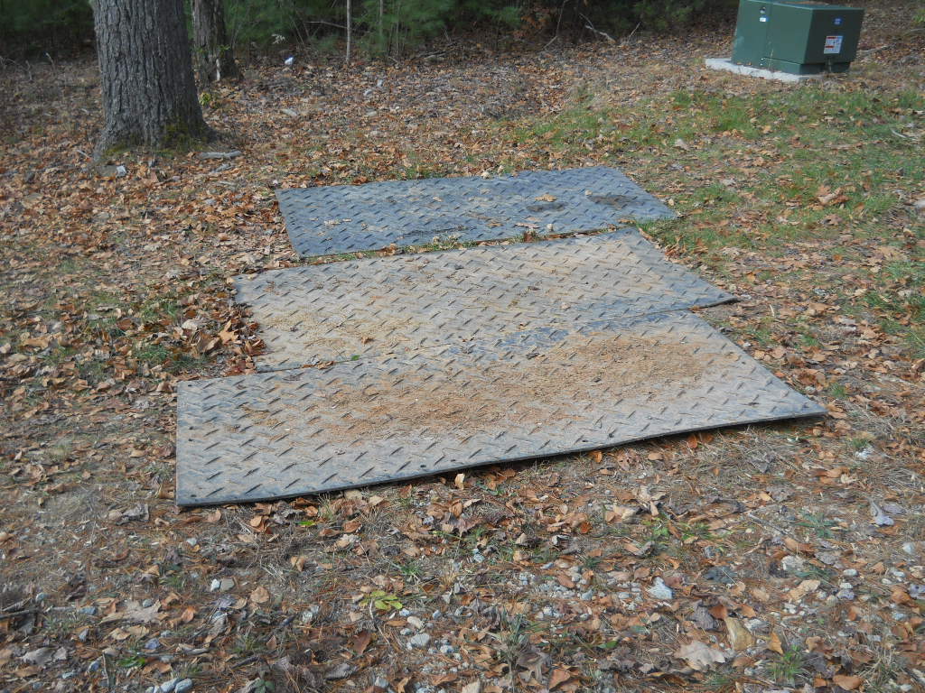
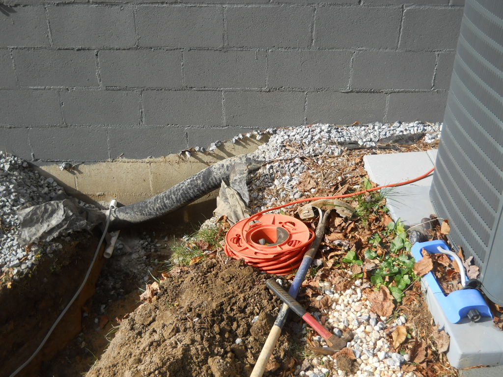
4. LOCATE UNDERGROUND UTILITIES & LAY DOWN MATS
Before you have any equipment come rolling across your land, it is important to locate all underground utilities to be driven over by heavy equipment. Then, lay down several heavy fiberglass & rubber mats (any good local driller should have these) that are engineered to spread the crushing force exerted by the tires of trucks rolling over them, to avoid smashing buried pipes under them.
© Copyright 2019, Home Architect, PLLC, All Rights Reserved Worldwide.
For instance, in the above image, there are 3 underground lightweight 4″ diameter black corrugated drainage pipes, draining the water from 3 downspouts coming from the front of the house, around the side and to the rear outpour area. These pipes are buried shallow. Only about 4″ to 6″ of dirt and gravel over the top of them. The main well drilling rig reportedly weighs 75,000 pounds. It has 3 axles and the rear two axles are dually, meaning 2 tires on each side. The front axle has the typical 2 tires. So: 4+4+2 tires = 10 tires = 7,500 pounds on each tire. Rand’s truck has a GVWR of 6,000 pounds. For the whole truck And it really weighs more like 4,500 pounds without people or stuff in the pickup bed. So: the well drilling rig has about 1-1/2 Honda Ridgeline trucks bearing down on each tire, transmitted to the ground, or around 15 pickup trucks worth of weight in the drilling rig. That’s lot of pressure being transferred to the earth. Sure to crush the dirt and shallow buried pipes under them. So that is why it is so important to spread the well driller’s fiberglass & rubber mats: to help prevent the heavy rig from smashing underground piping.
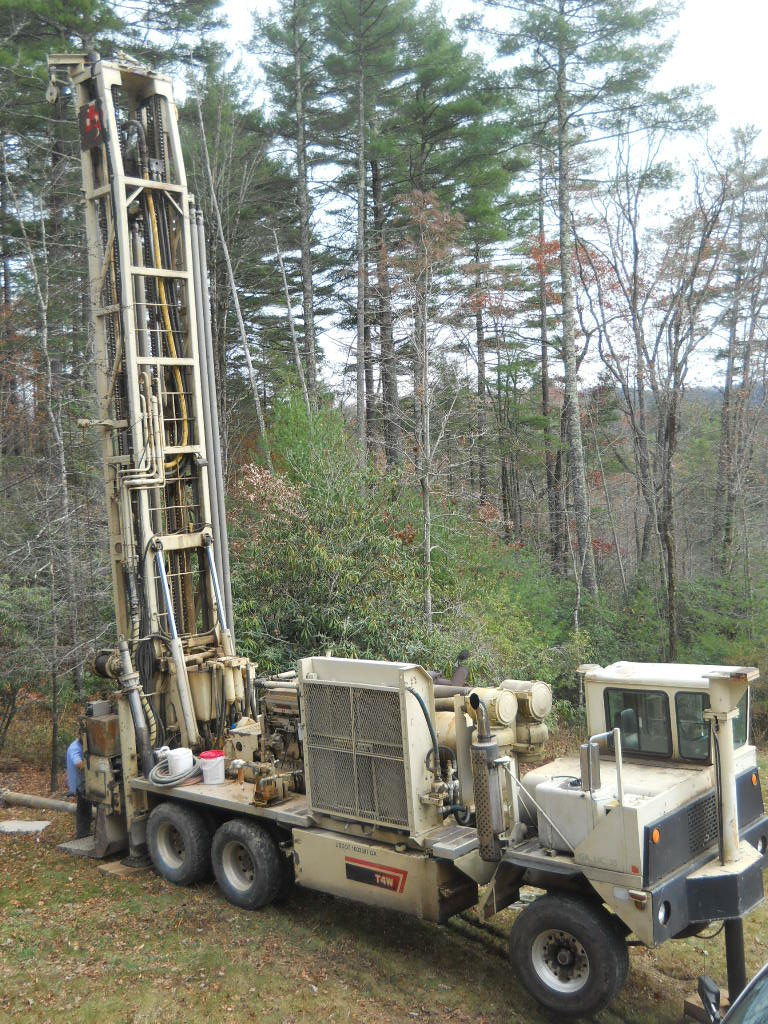
5. DRIVE IN DRILLING RIG TO YOUR CHOSEN WELL POINT
This is a big deal. This is a monster machine.
© Copyright 2019, Home Architect, PLLC, All Rights Reserved Worldwide.
Once the drilling crew (usually 2 or 3 people) gets this into place, backed up to the well drilling point, they lay down several heavy timbers and jack up the truck so the truck is level.
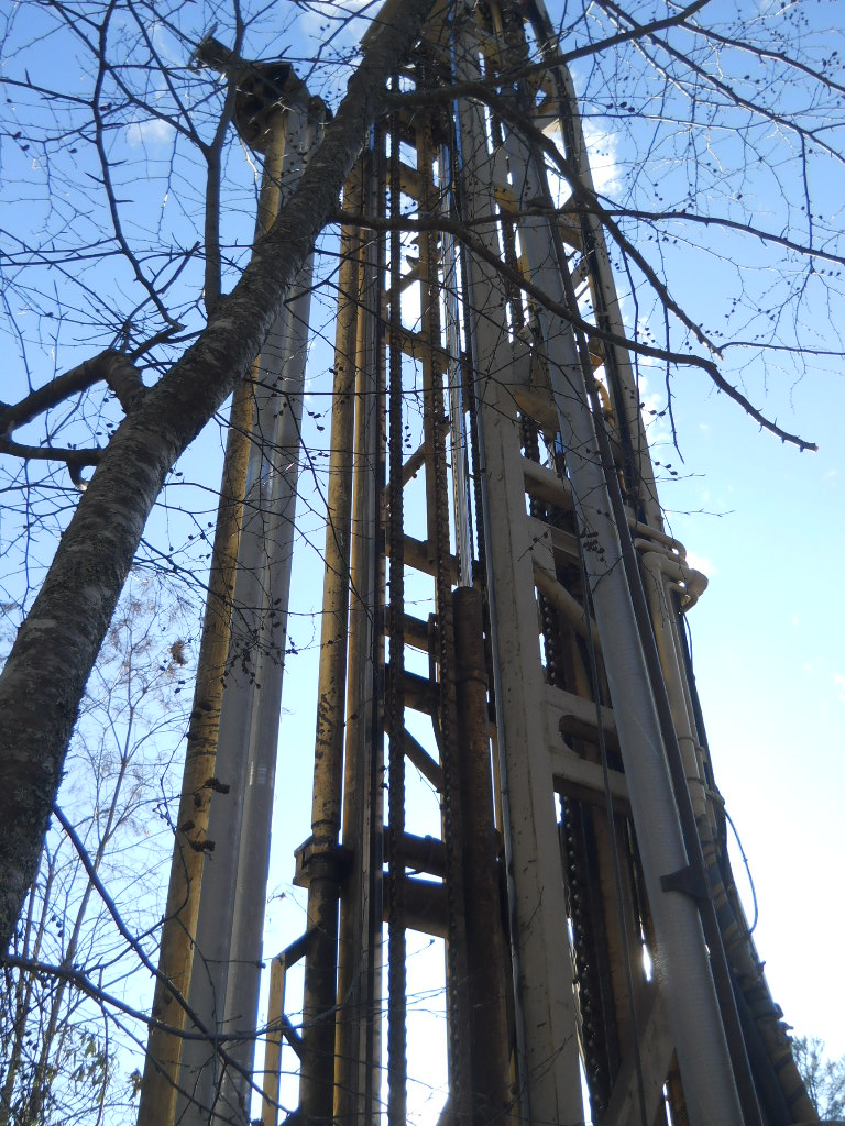
6. DRILLING
Then they tilt up the drilling mast and center it over the hole to be drilled. Then they install the drill bit rod, then start drilling down. When the first drilling rod is almost down all the way, the riggers pull another 25′ long steel rod and use the drill rig to thread it to the first one, then keep drilling.
© Copyright 2019, Home Architect, PLLC, All Rights Reserved Worldwide.
This process continues until they finally hit water or until you decide to stop spending your money on a hole in the ground.
© Copyright 2019, Home Architect, PLLC, All Rights Reserved Worldwide.
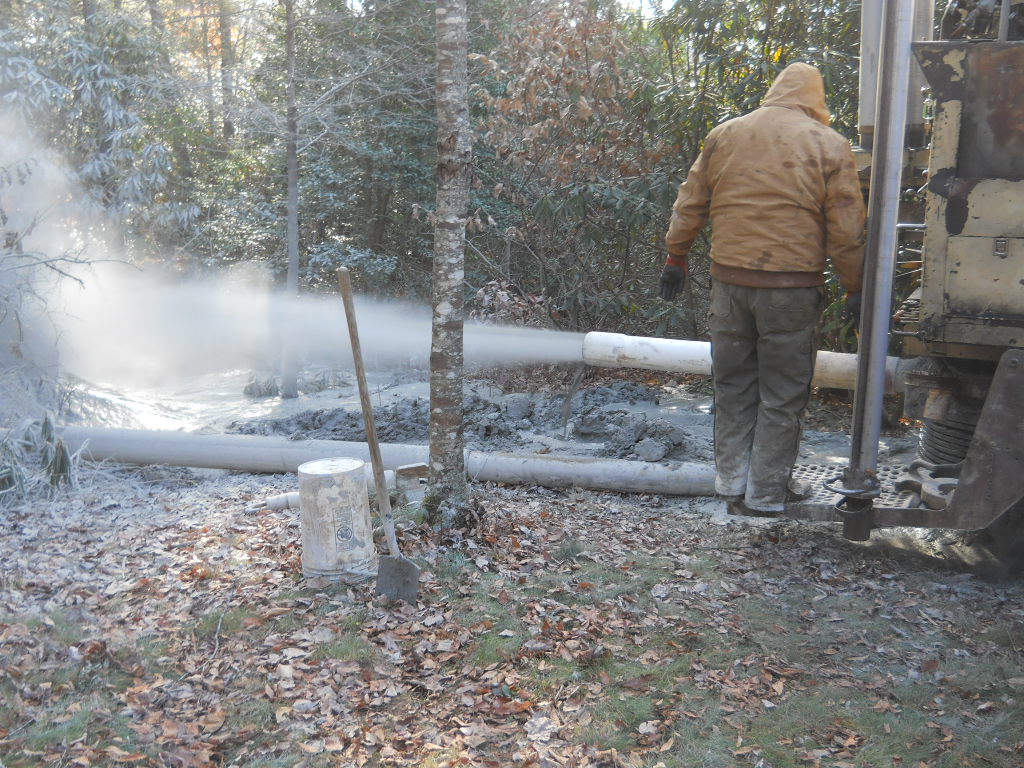
The riggers put a PVC blow-off pipe attached to the apparatus to remove the pulverized and liquefied rock that the drill continues to bore through as the drill descends. This blow-off pipe blasts the water-laden rock particles onto your land, usually into a harmless wooded area. You do not want to be in the way of this high pressure stream of rock dust and water spray. This process can continue for several hours or days until and if you hit water. In this particular situation, the owner of the well drilling company suggested after not hitting water for 800′ deep, that we pull everything up and try boring in another location on the land. The Architect/Owner of the house thought about this, but decided to continue.
7. WATER
He and his wife prayed about it and he got the impression that 875 was the magic depth. And so, the boring continued the next morning. A little while later, one of the drillers knocked on the front door of the Architect’s house. The Architect answered the door. The driller stood there smiling and saying: “We’re at 860′. We’ve got water!”
The Architect walked out to the well drill location and saw this:
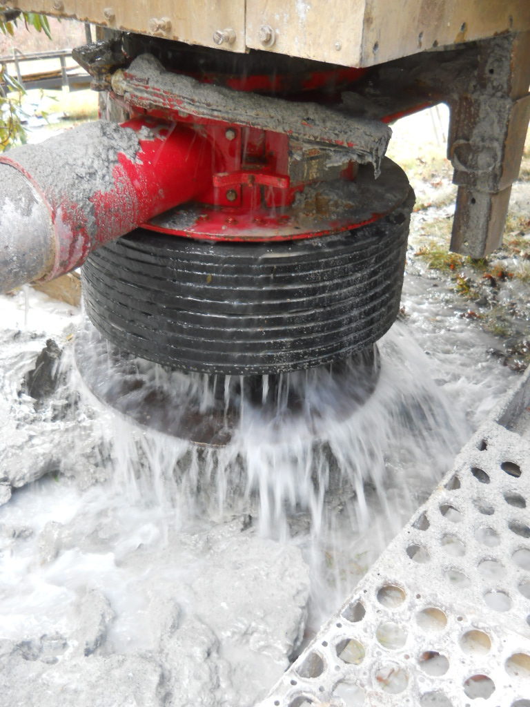
© Copyright 2019, Home Architect, PLLC, All Rights Reserved Worldwide.
The senior well driller shouted over the blasting sound: “We’ve got MORE than 100 gallons a minute! The golf course down the hill over there would kill for a well producing this much water!”
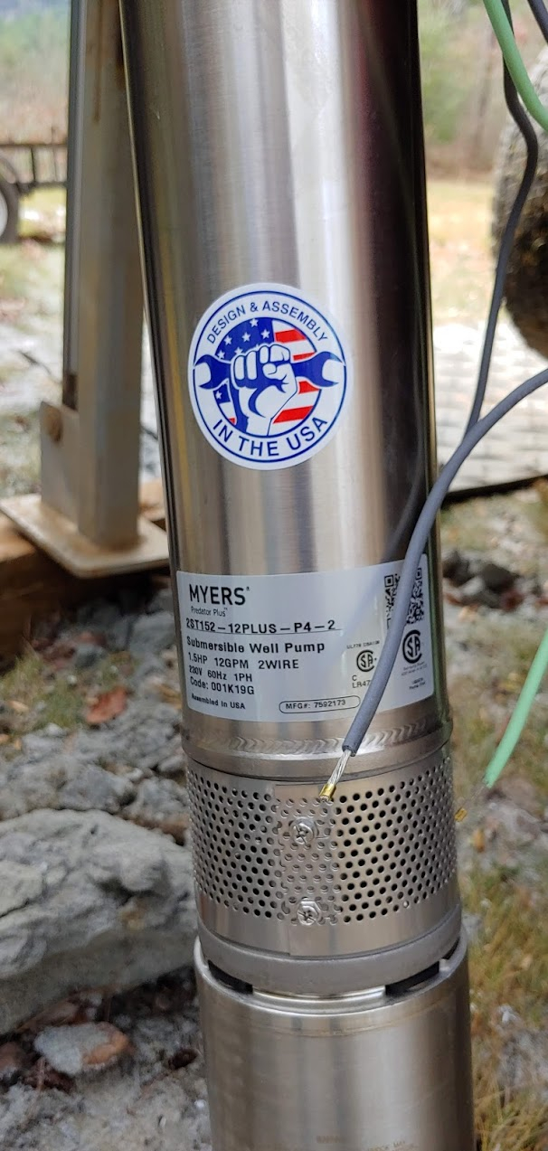
8. INSTALL PUMP & WIRE AND PIPING
© Copyright 2019, Home Architect, PLLC, All Rights Reserved Worldwide.
The Architect knew all he needed for his house was 8GPM. The drillers installed a Myers stainless steel 1-1/2 HP pump with 12GPM output. So, this is a very good situation. Gamble paid off. The water that blasted up the 860′ deep hole leveled off at 225′ below the ground. The pump was installed at 400′ below the ground. Each foot of 6″ diameter well hole holds 1-1/2 gallons of water in the rock bore hole. So there’s about 260 gallons of draw-down capability at all times above the intake mouth of the well pump screen. Which is an excellent arrangement.
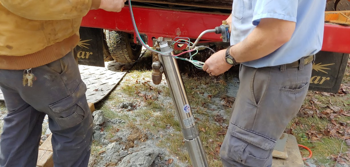
© Copyright 2019, Home Architect, PLLC, All Rights Reserved Worldwide.
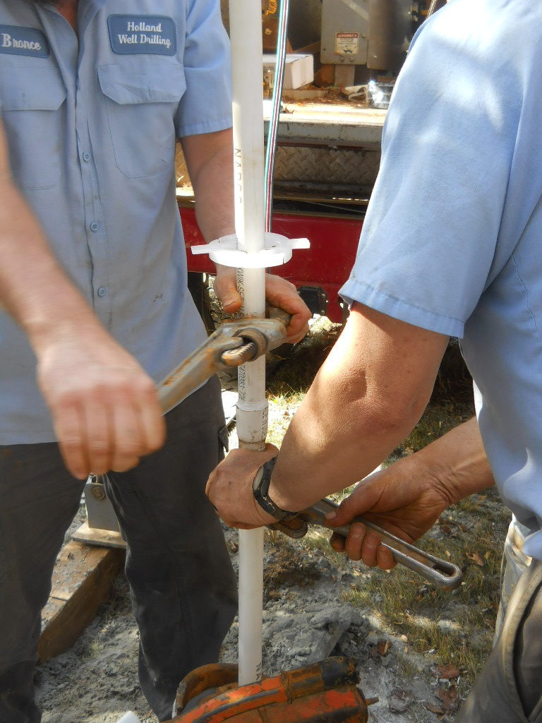
Here, you can see the riggers wiring the well pump just before inserting it into the well casing pipe.

© Copyright 2019, Home Architect, PLLC, All Rights Reserved Worldwide.
Schedule 80 PVC 1″ ID (interior diameter) 25′ lengths of piping was used, with threaded ends to attach to the well pump, as it was lowered into the well hole. Quality materials; quality workmanship by a top-notch local well drilling company: Dennis Holland Well Drilling.
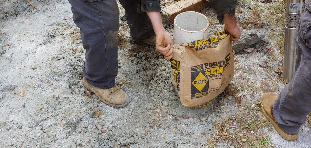
© Copyright 2019, Home Architect, PLLC, All Rights Reserved Worldwide.
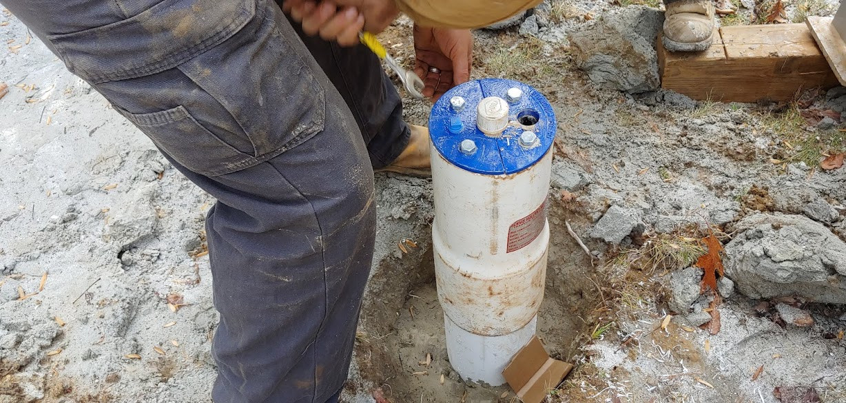
Above shows the final concrete top-most filling about the casing pipe. before this, there was quite a lot of Bentonite grout pumped around the casing. There was also what looked like about a coffee can of powdered chlorine dumped right down the casing, to sanitize the casing and the water in the hole. That must be pumped out over a several day period.
© Copyright 2019, Home Architect, PLLC, All Rights Reserved Worldwide.
Above is the well head top installation in progress.

© Copyright 2019, Home Architect, PLLC, All Rights Reserved Worldwide.
Above is the well pump and well piping above it, along with the well pump wiring, attached to the well pump piping.
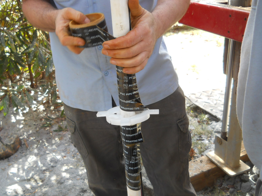
Below shows a spacer bracket that is sleeved onto the well piping, to center the piping in the bore hole.
© Copyright 2019, Home Architect, PLLC, All Rights Reserved Worldwide.
The well pump wiring also fits through a slot in the spacer bracket, to help support the wiring and hold it in place.
© Copyright 2019, Home Architect, PLLC, All Rights Reserved Worldwide.
This process continues, all the way along the PVC piping, as it is screwed together from the top, then gently lowered into the bore hole (in this case, for 400′ deep).
9. CONNECT TO HOUSE
© Copyright 2019, Home Architect, PLLC, All Rights Reserved Worldwide.
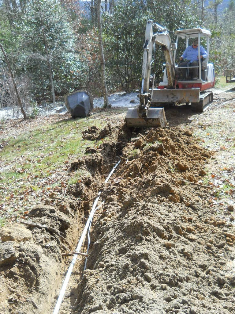
Here is the Driller’s trackhoe digging a trench in the side yard of the house and the connecting 1″ PVC pipe laid down in it, along with the electrical wiring, and those being covered over. About 18″ deep works in the area of the Country, as the frost line is above 12″.
Below, are the conduit and piping connection through bore holes made in the side foundation wall, giving access into the floor of the crawlspace under the house.
© Copyright 2019, Home Architect, PLLC, All Rights Reserved Worldwide.
It is important to try to find locations to drill through the foundation wall where there are not steel rebars, which could be difficult for the drill to handle. Here, we centered on a vertical block joint. Drilling went fast and sure. It is also important to select a location along the foundation wall where the water pipe can be buried over 18″ deep (in this environmental location) to prevent it from freezing. In more northern states, this would need to be twice as deep or more. Also: fill conduits and annular spaces around penetrating pipes with Lexel or silicone or polyurethane to keep out water and pests.
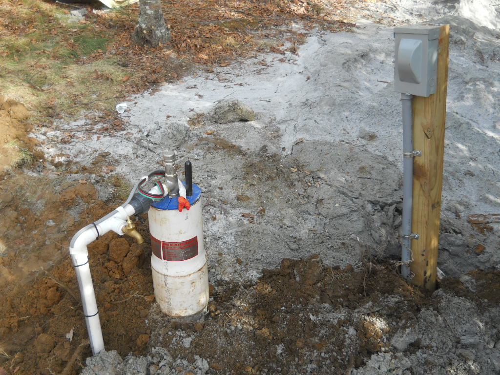
10. INSTALL ELECTRICAL BREAKER & POST AND COMPLETE WELL HEAD OUTSIDE
© Copyright 2019, Home Architect, PLLC, All Rights Reserved Worldwide.
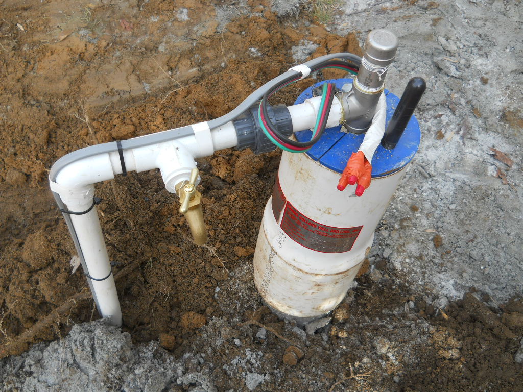
Here you can see the completed well head and the disconnect breaker mounted on a short post near the well. Note the stainless steel fittings at the well head (not galvanized).
Below you can see the County water sample spigot. It is not allowed to have any threads, as the County is concerned about siphoning back into the well from a hose.
© Copyright 2019, Home Architect, PLLC, All Rights Reserved Worldwide.
Also note the 2 information plates on the side of the well head. These indicate information about the well hole and about the well pump. For instance: The well hole is 860′ deep. It produces 100+ GPM. The static water level in the well hole is at 225′ below grade. The well pump is 1-1/2 HP 3 wire, and pulls up 12 GPM. The pump is set at 400′ below grade. All important information for future technicians working on the well.
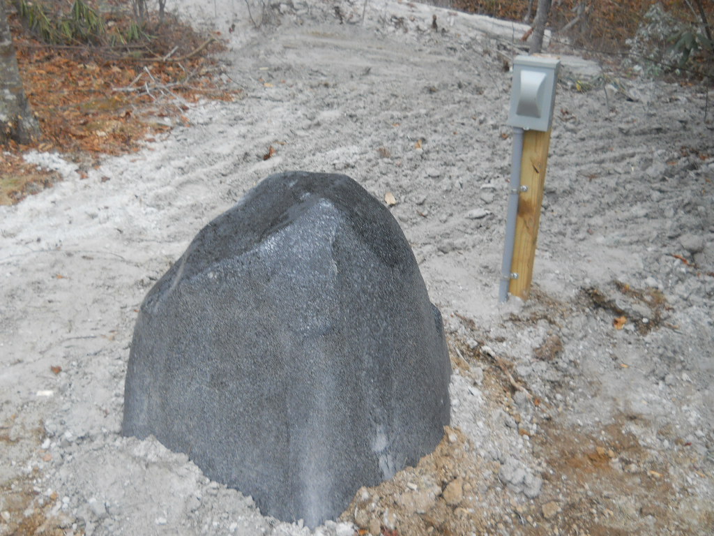
Below, you can see the minimal visual impact of the completed exterior installation:
© Copyright 2019, Home Architect, PLLC, All Rights Reserved Worldwide.
What appears to be a gray rock and a short post with a disconnect. Beneath the rock are several pieces of insulation, to guard against freezing. It is important to shovel dirt or take other precautions around the flat flange of the artificial rock to keep cold wind from blowing up into the rock underside, which could freeze the well head. That would be bad.
11. CRAWLSPACE PIPING, BLADDER TANK, WIRING
© Copyright 2019, Home Architect, PLLC, All Rights Reserved Worldwide.
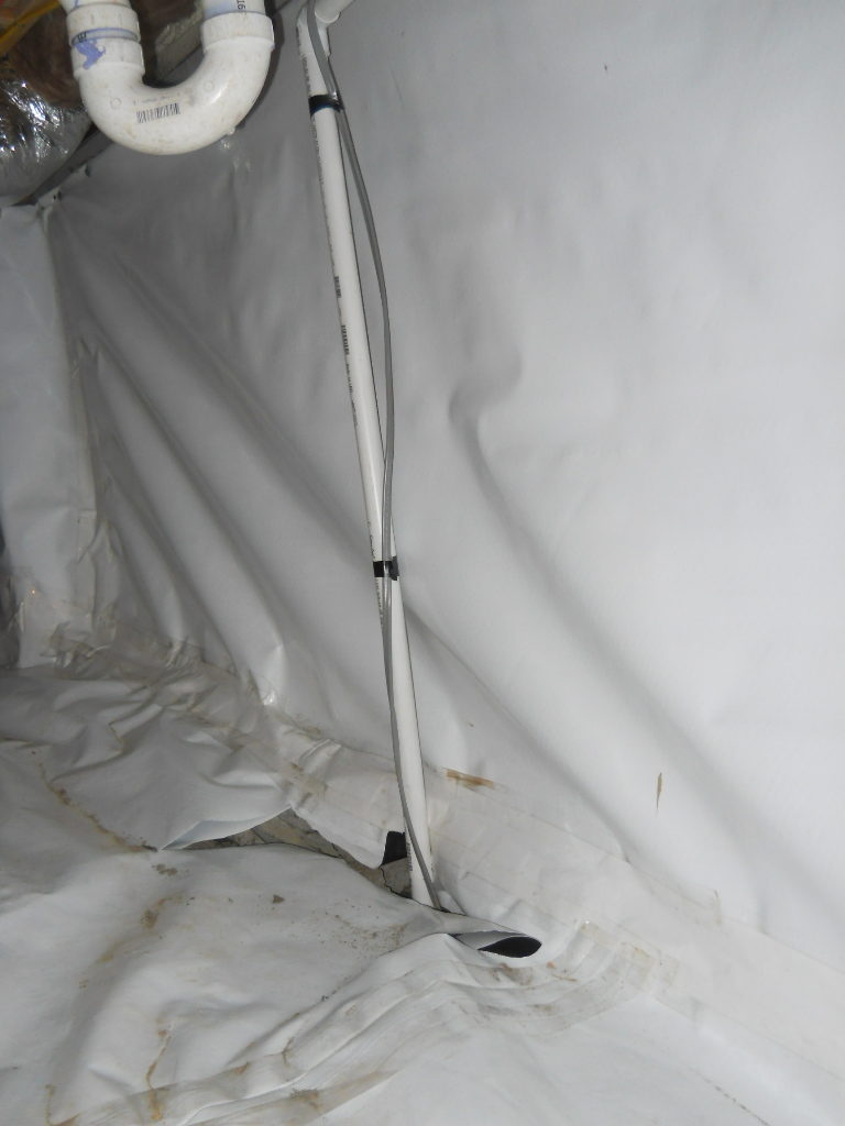
Here you can see the vertical water pipe with pump wire, coming up from the underground location in the crawlspace. This crawlspace is encapsulated, which in this case is 20 mil reinforced polyethylene (an excellent vapor barrier). Note that the well drillers installed clips to secure the piping to the wall, supporting it. Below, there is part of the horizontal run of the well water piping and its electrical wire.
© Copyright 2019, Home Architect, PLLC, All Rights Reserved Worldwide.
It is important to support water piping frequently, because water weighs 8.3 pounds/gallon. Doesn’t take much piping to get very heavy and we don’t want it to bend and break and spew water everywhere.
© Copyright 2019, Home Architect, PLLC, All Rights Reserved Worldwide.
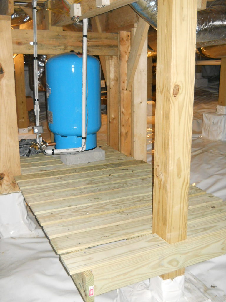
Above, here’s the nice pressure-treated wood plank platform the Architect built for the well treatment tanks, including for the well bladder tank. You can see there’s a lot of space left on the platform if the well water requires further treatment. Note the electrical boxes above the platform for power to the bladder tank filler switch and for other possible treatment tanks.
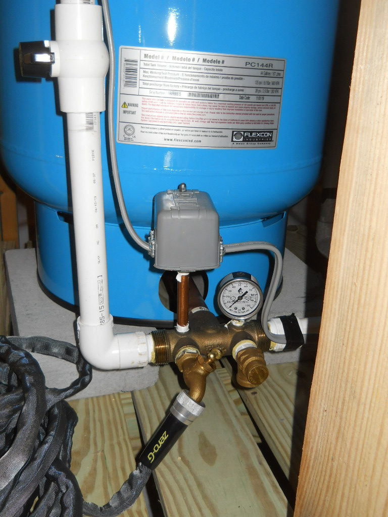
Below: you can see the pressure switch on-off near the base of the bladder tank. The bladder tank is a large blue tank filled in part with air and a membrane. When water fills the tank, the bladder is stretched up and puts the water under pressure, so it can push water into the piping serving the house, and get water to all the faucets in the house. When the tank is empty, the pressure switch turns on the well pump and more water gets pumped into it from the well. Note the black and white valve that allows the homeowner to shut off and turn on the water from the well. Note that the well water first goes into the pressure tank. This is important, otherwise the heavy pressure from the pump could rupture piping.
© Copyright 2019, Home Architect, PLLC, All Rights Reserved Worldwide.
Water in the tank is typically between 40 to 60 psi.
The hose at the base of the tank is used to drain the tank to remove contaminants, in this instance, to continue draining the chlorine from the disinfection powder during the well installation. It is impossible to test the water until all the chlorine is pumped out of the system.
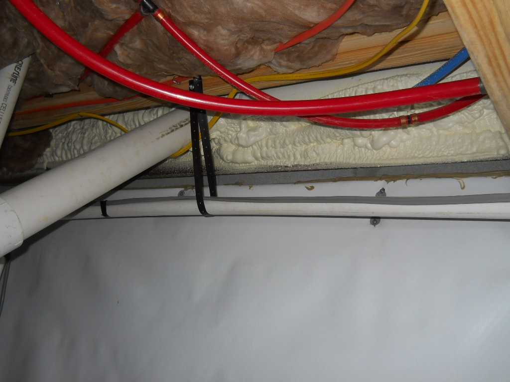
Below is a pipe loop over the well tank platform that the Architect requested, in case additional treatment tanks become necessary. This will make it simple to attach additional valves, if required.
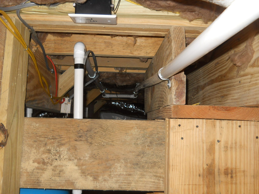
© Copyright 2019, Home Architect, PLLC, All Rights Reserved Worldwide.
Note the metal clips securing and supporting the water piping to the framing.
And here we are at the end of this journey: The overhead new well piping (with on-off valves) connecting to a new “in” location at the incoming water at the existing house water piping.
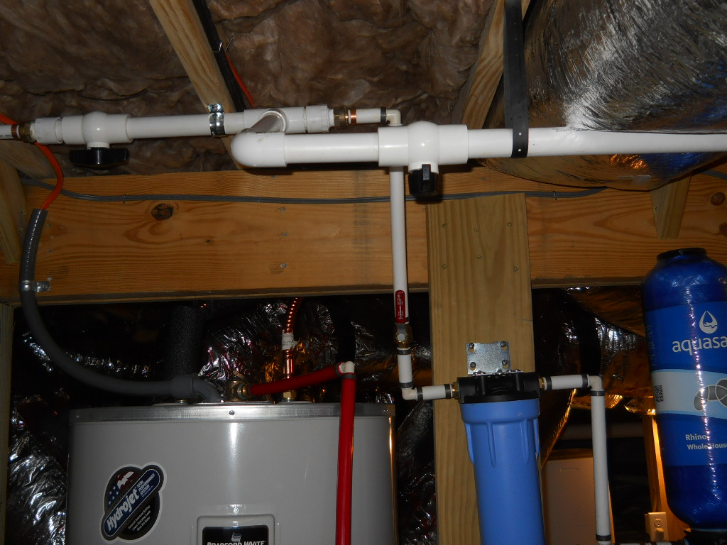
The existing water purification filter equipment is to the lower right. Notice the various clips to secure the piping. The Architect supervised all installation to insure that there were valves to allow 2 different source of incoming potable water for this house and to allow maintenance of both systems, and easy switching between them, so this house will always have a source of good, clean drinking water forever.